Parametric + algorithmic design
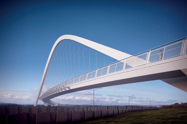
Dusk view of the Hendon Bridge looking south across the proposed State Highway 20.
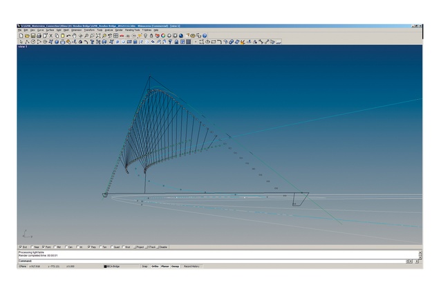
Rhinoceros model of the Hendon Bridge geometery.
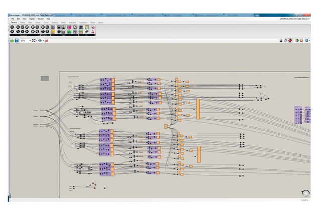
Grasshopper drier of the geometry for Point Resolution Bridge.
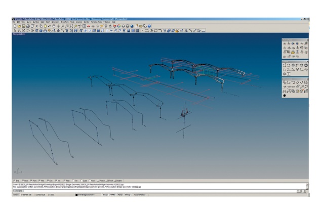
Resultant form generation and geometry for Point Resolution Bridge.
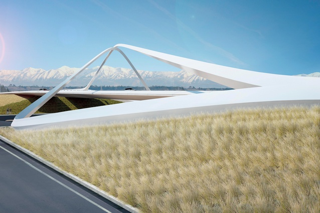
Daytime view, looking west, of the proposed Memorial Avenue Bridge, Christchurch.
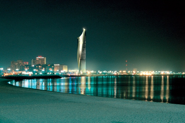
Dusk rendering of Al Hamra Firdous Tower, Kuwait.
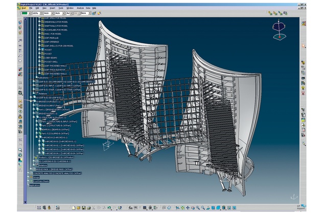
Parametric Digital Project model of QP Project, Doha, Qatar.
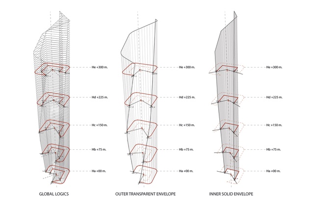
Geometry of Al Hamra taken from the Digital Project model.
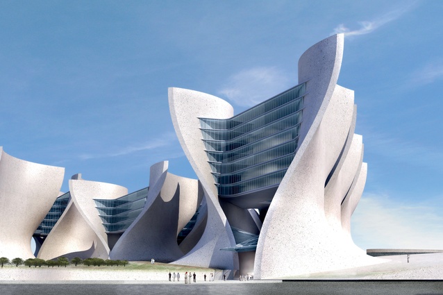
Daytime views of the QP Project, Doha, Qatar.
Digital models are explicit – every aspect of a design is well defined and can be described. A digital model, in which a design is represented explicitly, allows us, for example, to find the coordinates of any point, to produce plans, sections and elevations and, eventually, to build. But, parametric models are different.
A parametric model depends upon relationships between parts. A parametric model is defined by rules and constraints, which define aspects of a design and their relationships with each other. Changing a rule or constraint, or modifying a part of the model itself, has implications for the entire model.
With non-parametric models, the geometry is explicit but the rules are implicit – the model does not keep track of the rules. By contrast, parametric models have explicit rules and implicit geometry. The relationships and rules between the parts determine the geometric outcome.
Establishing rules or parameters within a model allows for several important advances. It provides the ability for real-time iteration, rather than rebuilding an entire model. A simple integer can be set as a parameter, for example, to drive the diameter of an arc that then drives the entire geometry of a bridge deck and everything that follows downstream, or the spacing of cables along an arch, or the panelisation of a complex surface.
Several tools have been developed in the past decade for creating parametric and algorithmic architectural models, such as Dasault Systèmes’ Catia and Solidworks, Gehry Technologies’ Digital Project (which employs the same parametric engine and was derived from Catia), Generative Components by Bentley Systems, Rhinoceros with Grasshopper by McNeel, and Revit and Inventor by Autodesk.
At Warren and Mahoney, we employ two pieces of software: Bentley’s GenerativeComponents and McNeel’s Rhinoceros with Grasshopper. Rhinoceros with Grasshopper provides an algorithmic editor that provides computational and parametric capability to Rhinoceros.
As examples, Warren and Mahoney has recently won several infrastructure design projects and has begun design work on several bridges using Rhinoceros and Grasshopper.
Hendon Bridge, Waterview, Auckland
Hendon Bridge in Waterview, Auckland, was designed in 2012 as a pedestrian link to reconnect the local community, split by the new State Highway 20 which joins Auckland’s motorway network together.
The aim was to create a very simple but beautiful trajectory with the deck curving three-dimensionally through space. The deck would, in turn, be supported by a simple but sculpted arch over the highway.
The deck plan was generated from three arcs, meeting tangentially and decreasing in diameter as the deck moved south. This geometrical definition standardised the components required to form the deck while still allowing for a complex and sinuously curved bridge.
As the arch crosses the highway in a near-perpendicular relationship, it straddles the curving deck underneath with the resulting theoretical surface on which the cables sit known as a hyperbolic paraboloid.
The bridge was designed and modelled parametrically to allow iterative testing and optimisation of the design and constructibility of the bridge. As the bridge comprised different components – arch, cables, posts – outriggers that were all interrelated, rules were established that could give a live and responsive model if these relationships were modified.
The deck was controlled by integer parameters that drove the diameter of the arcs that would then drive the entire geometry of the bridge deck and everything that followed downstream. The arch was similarly controlled – its centroid and section were driven as was its angular relationship in plan to the deck.
Point Resolution Bridge, Parnell, Auckland
In 2012, Auckland Council invited Warren and Mahoney to design a new pedestrian footbridge at Point Resolution to replace the existing structure, connecting St Stephens Avenue and Parnell Baths to Tamaki Drive.
It was determined that the bridge would be formed using three primary elements. A simple sculpted concrete deck would extend from the headland and protrude out into the harbour. This would be cradled by a highly expressive steel armature or exoskeleton. A simple, cantilevered glass balustrade, co-planar with the concrete deck, would provide barrier protection.
The steel supporting the deck was designed to pay homage to the original bridge by echoing its three arches. It began under the deck as a shaped column, separating to form the arches with the deck supported by the steel armature through discrete pin connections.
The bridge modelling allowed for design iterations to be produced quickly and tested against architectural and structural requirements.
The trajectory of the steel armature was described with a centroid and the form controlled with key sections along this curve, with both driven entirely parametrically allowing for iterative design testing without the need for manual remodelling.
The entire steel skeleton, with complex curvature of its surfaces, was documented solely in three dimensions and communicated with the fabricator without the need for traditional drawings.
Memorial Avenue Bridge, Christchurch
In 2011, Warren and Mahoney was part of the winning bid for the proposed Memorial Avenue Bridge in Christchurch. The bridge, essentially a grade separation of State Highway One, straddles Memorial Avenue, which is the primary link between Christchurch International Airport and the city.
The Christchurch City Council, Christchurch International Airport and the New Zealand Transport Agency all recognised the bridge as an opportunity to create a gateway – a simple but elegant form that would speak about the dynamism, excitement and speed of travel and echo the natural beauty of the Southern Alps.
After importing the road geometry, the bridge components were modelled in Rhinoceros with defining parametric values driven from Grasshopper. The diamond-shaped barriers on each side of the highway bifurcate and transform into two triangular-sectioned arches that rise diagonally over Memorial Avenue and State Highway 1. The longer primary arch was arranged to create an alignment perpendicular to Memorial Avenue and provide a symmetrical gateway.
The centroid trajectory of the arches was described parametrically with integer offsets and the form of the bridge controlled with key sections along this curve. Both the trajectory of the curve and the form of the sections were entirely driven allowing for iterative design testing without the need for manual remodelling.
The structural team imported this simplified centroid and section model into Strand where the structural analysis of the form was made, again increasing the interoperability between the teams and efficiency.
Al Hamra Firdous Tower, Kuwait City
Al Hamra Firdous Tower, designed while I was working at Skidmore, Owings & Merrill in New York, is a 412m-high office building in Kuwait City, completed in 2011.
Formally, the tower was a hollowed square mass with a quarter of each floor plate removed, starting from the south-west corner at ground and rotating counter-clockwise to the south-east corner over the height of the tower. Though the tower appeared to rotate, it was the absence, or courtyard-like centre, that was rotating and creating the formal gesture of the tower.
The building offers optimal transparency to the north and east, and west to the Gulf, but a nearly uninterrupted stone façade to the south, protecting the building from the desert sun.
The team used two modelling programmes – Rhinoceros (Rhino) and Gehry Technologies’ Digital Project in conjunction with visual basic scripting. Rhino was used to design and test iterations of the massing of the tower with Grasshopper driving key formal parameters. These included parameters driving the overall morphology of the tower and the subtraction of the internal court generating the form of the tower. Digital Project was employed in areas of particular geometric complexity and where issues of iteration and testing were anticipated.
Particular application of this was in the design of the 25-metre-high lobby, spanned by a structural concrete lamella. The design of this required an iterative process with constant input from the structural design team, the contractor and the client.
Visual Basic scripting was employed in the optimisation of the stone cladding to the complex curvature of the shear walls defined by the subtraction of the floor plate.
QP Project, Doha, Qatar
The QP Project is a 450,000m2 office complex and masterplan located to the north of Doha, Qatar.
The campus was designed to house a population of over 4,000 employees and included large office buildings, an auditorium, conference centre, medical facilities, a ballroom, recreation facilities, a stadium, professional and industrial training centres, and a masjid.
The scheme derived its architectural language from a desert morphology, a precise use of geometry and an environmental response to the harsh climate. The building block of the campus – and the generator of the planning grid – was the ‘leaf’, the external core element of the building.
The genetic make-up of this building block was then propagated over the site and informed all other aspects of the planning and design of the complex.
The leaves were conceived as massive, monolithic and sculptural forms with a suggestion that they were a natural part of the desert. The tectonic steel and glass bridges suspended between the leaves that housed the offices had the contrasting sharp lines of a man-made object.
The size, complexity and morphology of the project demanded sophisticated documentation and analysis tools. The project was fully designed and documented in Digital Project.
The model evolved with the basic building blocks of the leaves being the first parametric component built. This became the basic parametric DNA to which all the subsequent elements followed.
As further parameters were added to the model, the management and interrelationship of these became crucial. Off the back of this project model, analysis software could directly import the model to provide accurate and meaningful feedback that took into account the form and orientation of the buildings.
The model was imported into RadTherm for energy analysis. Fluent was used to examine the effects of the prevailing wind through the space. The structural team imported the model into Strand where the structural analysis of the form was made.
A full BIM model was ultimately created allowing full three-dimensional coordination, structural analysis and thermal modelling in an attempt to optimise the building’s performative design along with four-dimensional simulations of construction phasing.
The use of parametric three-dimensional models allows for iterative change, optimisation of form, optimisation of construction efficiency and increased interoperability with consultants. Ultimately, however, these models are powerful only when they allow more time to explore, test and design.